Chinese
 English
 français
 italiano
 español
 português
 Nederlands
 日本語
 한국의




Kategorien
Heiße Produkte
Patent CN215587201U - Battery Sorter with Pressure Sensing
Oct 20,2026Cells ride in pressure-sensing detection bases along a conveyor; an electric cylinder with a rubber pusher diverts rejects into a sorting box - and an emergency-stop bolt can lock the drive shaft.
Full specification and drawings: CN215587201U on Google Patents
After a battery is produced it still has to be checked - and in the prior art that check was done the slow way. The specification of CN215587201U states the problem plainly: in the existing technology, batteries were tested one by one in batches by hand after production and only then sorted, so sorting efficiency was low. A line that has to stop for manual testing cannot feed the next process step.
The patent replaces the manual step with an inline station. Batteries travel on a conveyor in detection bases, a pressure sensor in each base judges the cell while it moves, and an electric cylinder with a rubber pusher diverts any out-of-spec cell into a sorting box without stopping the line.
Patent Information
| Publication number | CN215587201U |
| Application number | CN202122171465.1U |
| Title (original) | 一种电池生产用的分选机 (Inline Battery Sorting Machine with Pressure Sensing) |
| Inventors | Huang Zhengyao (Dany Huang); Chen Lucai (Tobey Chen) |
| Current assignee | XIAMEN TOB NEW ENERGY TECHNOLOGY Co., Ltd. - the registered entity of TOB NEW ENERGY |
| Filing date | 9 September 2021 |
| Grant date | 21 January 2022 |
| Document type | Utility model (kind code U) |
| Legal status | Active |
| Anticipated expiration | 9 September 2031 |
| Drawings | 7 figures |
| Official record | CN215587201U on Google Patents |
The Production Problem This Patent Solves
Post-production sorting was a manual bottleneck. Once batteries are manufactured they must be checked and sorted before they can be used or shipped. The prior art did this by testing batteries in batches by hand and then sorting them, and the specification identifies that manual batch testing as the reason sorting efficiency was low.
Inline judgement needs a sensor on the line. To sort without stopping, the machine has to judge each cell as it travels. This design puts a pressure sensor in every detection base on the conveyor, so the measurement and the diverting decision both happen while the belt runs.
CN215587201U therefore targets two outcomes the specification claims explicitly: higher practicality - automatic detection and diverting, with detection bases that can be swapped for different detection equipment; and higher stability - smooth push-out and return of the pusher, plus emergency braking of the conveyor.
How the Mechanism Works
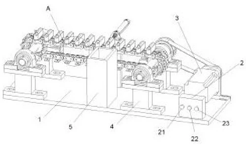
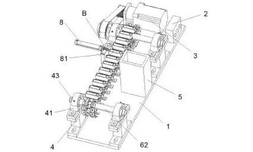
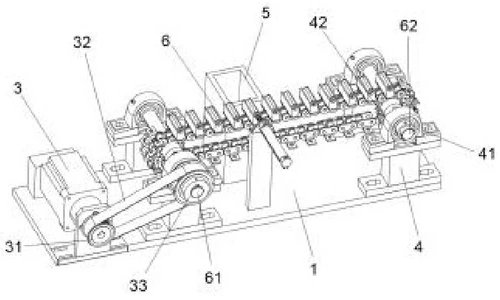
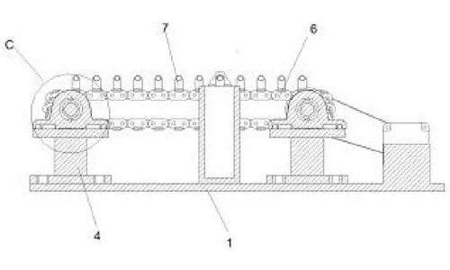
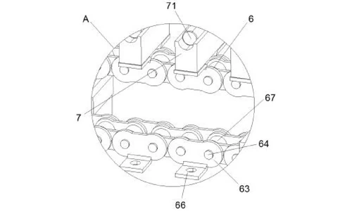
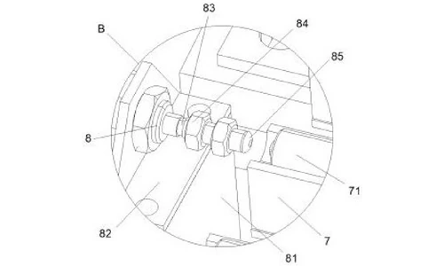
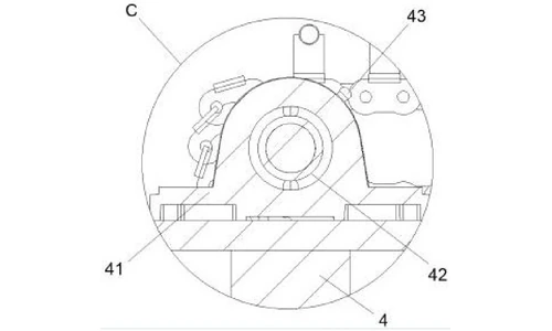
The machine is a workbench-scale line: a controller on the right, a motor behind it, two belts and a driven shaft carrying the main conveyor, and a divert station on the far side of the belt. Figures 1-3 show the overall machine from three perspectives, Figure 4 is the overall cross-section, and Figures 5-7 enlarge details A, B and C.
Control, drive and the two-belt transmission
A controller sits on the right of the upper face of the workbench, with a start button, a stop button and an emergency-stop knob in sequence across its front face. A motor behind the controller turns a driving wheel; the first conveyor belt over the driving wheel reaches a driven wheel on the left, and inside that driven wheel is the drive shaft. The drive shaft carries the second conveyor belt, whose far end runs on a driven shaft. All controls, the motor and the pressure sensors are electrically connected to the controller and to an external power supply.
Detection bases with pressure sensors
Detection bases are carried on the second conveyor belt, and a pressure sensor is fitted inside each base to hold a battery. The operator places cells into the bases at one end of the belt; as each base travels, its pressure sensor judges the quality of the cell and sends the parameters to the controller.
Divert station with electric cylinder
On the rear side of the second conveyor belt a fixed block carries a connecting plate, and the plate carries an electric cylinder at its rear end. The cylinder drives a telescopic rod forward; at the rod front is a driving cushion block made of rubber so that a pushed cell is not damaged by excessive force. The sorting box is placed opposite the telescopic rod, across the belt. A limit block, in interference fit on the rod between the rod and the cushion block, stops the rod from striking the connecting plate when it retracts.
Modular conveyor and swappable detection bases
The second conveyor belt is assembled from clamping plates, clamping shafts and clamping columns, with each clamping column in interference fit with a clamping shaft - the specification states this lets the belt length be increased or decreased as needed. Fixing plates on both sides of the clamping plates are bolted to the detection bases, so a detection base can be unbolted and replaced with different detection equipment when the sorting requirements change.
Bearings and emergency braking
Bearings at both ends of the drive shaft and the driven shaft support the shafts. Each bearing sits inside a connecting frame mounted on a fixed base, and an emergency-stop bolt is threaded into the outer end of the connecting frame. In an emergency the operator presses the emergency-stop knob, which forces the electric cylinder and the motor to shut down, then screws in the emergency-stop bolt so it locks the bearing - braking the drive shaft and the second conveyor belt.
Working sequence as published: the machine is connected to the external power supply and the start button is pressed; the controller runs the motor, which turns the driven wheel through the driving wheel and the first conveyor belt, driving the drive shaft and the second conveyor belt so the detection bases travel smoothly; an operator loads a battery into each detection base at one end; the pressure sensor judges the battery and sends the parameters to the controller; when a battery does not meet the quality standard the controller starts the electric cylinder, the telescopic rod extends, and the rubber cushion block pushes the battery into the sorting box; in an emergency the emergency-stop knob cuts power and the emergency-stop bolt brakes the shaft through the bearing.
Claimed Benefits
| Benefit | Mechanism responsible |
|---|---|
| Automatic detection and diverting on the line | Pressure sensor in each detection base; electric cylinder pushes rejects into the sorting box |
| Adaptable to other sorting criteria | Detection bases bolted to fixing plates can be removed and swapped for different detection equipment |
| Adjustable conveyor length | Clamping columns in interference fit with clamping shafts on the second conveyor belt |
| Cells not damaged during rejection | Rubber driving cushion block on the telescopic rod |
| Smooth push-out and return; emergency braking | Limit block on the rod; bearings with threaded emergency-stop bolt on the connecting frame |
How It Compares with Manual Batch Testing and Sorting
The prior art tested batteries in batches by hand and then sorted them, and the specification identifies that manual batch testing as the reason sorting efficiency was low. This machine tests and diverts each cell as it travels along the conveyor.
| Dimension | Conventional approach | This patent design |
|---|---|---|
| Testing | Off-line, batch-by-batch manual testing | Pressure sensor in each detection base tests cells inline |
| Diverting | Manual handling of rejects | Electric cylinder with a rubber pusher pushes rejects into a sorting box |
| Adaptability | Fixed testing arrangement | Detection bases are bolted and swappable for other sorting criteria |
Where This Technology Is Used Today
CN215587201U covers the pressure-sensing conveyor architecture of TOB's inline battery sorting equipment - the compact line-end station that checks each cell while it moves and pulls the rejects out without stopping.
- Battery sorting / grading machines - 18650 sorting units for pack assembly lines
- Complete cell production lines - the inline environment this sorter is designed to sit in
Related equipment enquiries: request a quote
Frequently Asked Questions
What does patent CN215587201U cover?
It covers an inline battery sorting machine for battery production. A controller on the workbench runs a motor whose driving wheel turns a driven wheel through a first conveyor belt; the driven wheel drives a shaft that runs the second conveyor belt, on which detection bases travel. Each detection base holds a pressure sensor, and an electric cylinder with a rubber driving cushion block pushes out-of-spec cells into a sorting box.
Why was post-production sorting inefficient in the prior art?
The specification states that batteries were tested one by one in batches by hand after production and only then sorted, and that this made sorting efficiency low. Replacing that manual batch testing with an inline pressure-sensing conveyor is the problem the patent solves.
How does the machine judge whether a cell is unqualified?
A pressure sensor is fitted inside each detection base on the second conveyor belt. As the belt runs, the sensor judges the battery in the base and sends the measured parameters to the controller. When a battery does not meet the quality standard, the controller starts the electric cylinder and the telescopic rod pushes the cell into the sorting box.
Can the machine be adapted to other sorting criteria?
Yes. Each detection base is bolted to fixing plates on the conveyor, so it can be removed and replaced with different detection equipment when the sorting requirements change. The second conveyor belt is also modular - clamping columns in interference fit with clamping shafts let the belt length be increased or decreased.
How does the emergency stop work?
In an emergency the operator presses the emergency-stop knob, which forces the electric cylinder and the motor to shut down. Screwing in the emergency-stop bolt, which is threaded into the connecting frame around the bearing, locks the bearing and brakes the drive shaft and the second conveyor belt.
Is patent CN215587201U still in force?
Yes. TOB NEW ENERGY holds this granted utility model; it is Active, filed on 9 September 2021 with anticipated expiration on 9 September 2031.
Full specification and drawings: CN215587201U on Google Patents
 Abonnieren Sie uns